As I mentioned in the first Perspective Hacks, I was very taken with Bruce McEvoy's model of a simplified perspective situation:
Having come into possession of a clear plastic cube, I decided to create a physical model of it.
The first step was to place the picture plane so as to divide the cube in half, so that the distance from the ground plane to the centerpoint, one half the cube's height, would equal the distance from the viewpoint to the picture plane.
I cut the picture plane out of an old CD jewel box, inscribed the horizon line, vertical center line, and circle of view on it, and mounted it at the halfway point.
On the facing side of the same piece, I made a line from the middle of the bottom edge to the centerpoint, representing the viewer's eye height and viewpoint.
I made a rectangular opening in a square sheet of paper to mask off part of the picture plane, leaving a window to reveal the space on the far side. Note that the center of the picture window is not the same as the center of vision.
The window could be any arbitrary size, shape, or position in the plane, although usually the center of vision (the main vanishing point) is somewhere near the center of the picture.
The space behind the window is defined by two inclined planes at 45˚, meeting at the horizon and inscribed with a grid of orthogonals and diagonals.
Figuring out how to plot this grid was a puzzle, and led to some interesting insights into the wider subject of space division in a rectangle, so I'll address that in a separate installment. Basically, the inclined planes mimic the appearance of infinite ground and sky planes receding to the horizon, but contained in the half-cube opposite the viewpoint.
I tried to get a photo from as close as possible to the actual viewpoint. It should give the impression of looking into 3D space (on a really gloomy, depressing day in some sort of post-apocalyptic dystopia).
Saturday, November 22, 2014
Perspective hacks V: Villard's Railroad
In Perspective Hacks IV: The Box, I mentioned the problem of plotting a perspective grid on a 45˚ inclined plane to represent the view through the window in the picture plane. The box has two mirror image planes meeting at the horizon line; here is just the bottom half for simplicity's sake:
I wasn't sure how to approach the problem of plotting the grid at an angle until I tried drawing out the arrangement in a side view.
Here, the square on the left represents the box, with the viewpoint at the halfway mark on the left side. Points on the ground at regularly spaced distances D1 - D5 would reflect rays of light to the viewer's eye, intersecting the Picture Plane at the bottom for D1, the 1/2 point for D2, the 1/3 point for D3, and so on. When the Inclined Projection Plane is placed at a 45˚ angle between the Picture Plane and the Principal Point, the rays would intersect it at bottom for D1, then 2/3 for D2, 2/4 (or 1/2) for D3, 2/5, 2/6 (1/3), and so on.
Here is where my perspective wanderings finally looped back to the Hor:ratio project. One of the proportional tools included in Hor:ratio is the Armature of the Rectangle, a simple yet profound pattern of diagonals that creates fractional divisions of each side by 2, 3, 4, 5.
See how the simplified armature corresponds to the lower right quadrant of the square in the side view. The division of the square by 3 at the intersection of the ray with the diagonal also divides the diagonal itself 2/3 from the top.
Using this knowledge, I could find the 2/3 point on the inclined plane and use it to build the grid according to the Railroad Track Hack.
For some reason I had never noticed the similarity between the Railroad Track Hack and Villard's Diagram, which I had also come across in course of the Hor:ratio research, Initially, I had seen it applied to particular proportional settings, such division by 9, used in book page layouts. Suddenly I realized that it could be used to divide a rectangle by any fraction!
Starting with one half:
take a diagonal from the intersection of the 1/2 line and the edge up to the far corner
draw a horizontal line through the intersection with the opposing main diagonal to divide by 1/3
draw another diagonal from the intersection of the 1/3 line and the edge up to the far corner
draw a horizontal line through the intersection with the opposing main diagonal to divide by 1/4
Repeat for 5,6,7 and so on.
Thus, we can divide the rectangle into an infinite number of smaller and smaller fractions.
However, we don't have to plod though all of the steps to reach a desired fraction . If we combine the principals of the Armature of the Rectangle with Villard's Diagram, we can cut out steps and simplify the design by leapfrogging to the nearest simple division and building from there.
The procedure for building the VD is the same as for the RTH, but instead of thinking of it as equal distances receding in space, we see it for what it is - the progressive division of the rectangle into proportionately smaller fractions. This is indeed the principle upon which perspective is based: The apparent size of an object diminishes in direct proportion to its distance from the observer.
Perspective Hacks I
Perspective Hacks II
Perspective Hacks III
Perspective Hacks IV
Perspective Hacks V
Perspective Hacks VI
Perspective Hacks I
Perspective Hacks II
Perspective Hacks III
Perspective Hacks IV
Perspective Hacks V
Perspective Hacks VI
Sunday, November 16, 2014
Perspective Hacks VI: Polygons
I got started thinking about constructing polygons in perspective last summer when I was attempting to paint a beach umbrella. I realized that the key to this was to draw the hexagonal perimeter correctly; only with that structure in place would I be able to deal with the stretched fabric, windblown flaps, and off kilter angles in the scene.
Most of the instructions I have seen for drawing hexagons and other polygons in perspective require that you first draw the shape in plan view, then use a variety of techniques to project it onto the picture plane. This is accurate but time consuming and becomes more complicated when the object is at an arbitrary angle rather than parallel or perpendicular to the ground plane. I wanted a way to do it "on the fly," that would be more accurate than just eyeballing it but less rigorous than the full-on architectural technique.
I suspect most sketchers are familiar with the trick for making a circle in perspective, where you start with a square, mark it off with horizontals, verticals and diagonals, and inscribe the circle using these as guides. Then, it is relatively easy to draw the square and guides in perspective, and rebuild the circle in the same way. If you would like a refresher, I posted on the topic here, or there are many versions of the tutorial on line.
It turns out that this procedure also provides all the information you need to create a hexagon. Here is the basic circle setup:
Note that the intersections of the diagonals in the four quadrants locate the 1/4 divisions of the sides. Now, here is the same diagram with the hexagon inscribed and the horizontal 1/4 and 3/4 points extended out to the sides.
The intersections of the 1/4 and 3/4 lines with the circle locate the 4 middle corners of the hexagon, and the center line locates the top and bottom.
With a bit of practice, this procedure can be carried out in a square drawn in perspective. While not as mathematically accurate as a projection from a plan view, it is much quicker and easier to incorporate into a sketch.
Here's a real sketch, just to demonstrate that it can be done. I find it helpful to label the half and quarter intersections before drawing the circle and hexagon, to reduce confusion.
I also find that having practiced drawing hexagons this way, I am better at drawing them freehand.
BTW, although beach umbrellas are usually hexagonal, rain umbrellas are typically octagonal. No idea why this is, but octagons are even easier to do with this technique - just draw radius lines from the center through the same 1/4 points, and the circle is divided into eight equal segments.
Pentagons, on the other hand, are harder, but doable. However, we have to accept a further level of inaccuracy, as the pentagon does not succumb to ordinary fractions like halves and quarters.
Here is a diagram of a pentagon inscribed in a circle contained in a square:
You can see that the vertices of the pentagon almost map on to the intersections of the horizontal line indicating the 1/3 division of the square, and the vertical lines indicating the 1/5 and 4/5 divisions. Not close enough for a mathematician or an engineer, perhaps, but close enough for a sketcher who is making an artistic statement, not a blueprint.
So how do we find those points in a way that can be easily applied to a square in perspective? Here we have to go beyond the basic circle trick and invoke the magic of the armature of the rectangle.
Those of you who have checked out my Hor:Ratio project will remember this simple diagram with amazing powers of division. It locates divisions of a square or rectangle by 2,3,4,5, and their multiples using only straight lines added to the basic British flag design we already know from the circle trick.
Here's the pentagon with the relevant armature lines:
Here's just the 1/3 division:
And the 1/5 and 4/5 division:
and finally, the real version as proof of concept:
That schmutz in the corner is on my scanner platen, not your computer screen, BTW.
Perspective Hacks I
Perspective Hacks II
Perspective Hacks III
Perspective Hacks IV
Perspective Hacks V
Perspective Hacks VI
Saturday, November 15, 2014
Stare-I/O
Stare-I/O is an intuitive solution to the problem of scaling sight size measurements up or down and projecting them onto a canvas or other working surface.
The name, Stare-I/0, is meant to suggest the use of two identical components (speakers/rulers) interacting with the human perceptual system to convey spatial information.
Note that this all assumes we are scaling up, and using a landscape (horizontal) format. To scale down, we would start with the proximal ruler and transfer to the distal, and for a vertical format we might rotate the rulers 90˚to measure the longer side.
Using a picture plane
The name, Stare-I/0, is meant to suggest the use of two identical components (speakers/rulers) interacting with the human perceptual system to convey spatial information.
I/O (Input/Output) because Stare-I/O takes an input in the form of a sight size measurement, runs a transformation on it and outputs it as a scaled measurement. And you end up doing a lot of staring when you use it.
Stare-I/O provides a way to hold the measuring tool at a constant distance from the artist's eye, which is crucial to taking consistent measurements. If the scale of the drawing matches the apparent size of the scene from the artist's point of view, then measurements can be transferred directly to the canvas. (I'll be referring to the working surface as the "canvas" even though it can be paper or other material). I added a comment below about a method of direct sight size drawing.
If, however, the apparent size needs to be scaled up or down, we need a constant factor to multiply or divide by. Stare-I/O is intended to be used primarily in situations where the canvas is supported by an easel or pochade box at a relatively constant distance from the artist.
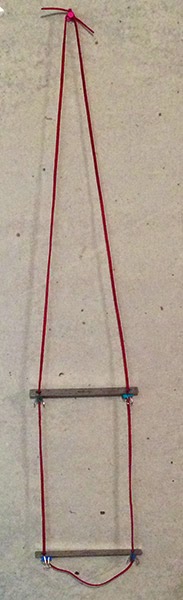
The rulers are used to hold a measuring tool at a constant distance from the artist's eye, but now there are two constant distances to work with. The basic principle is that measurements taken on the farther (or "distal") ruler will appear larger when applied to the nearer (or "proximal") ruler. If we take a measurement on the distal ruler - let's say we use the ruler's own markings and find that the apparent width of a distant building equals one inch on the ruler - and then compare it with that "same" inch on the proximal ruler, the proximal inch will appear larger. How much larger is in proportion to the change in distance from our eye. If the proximal ruler is half as far as the distal, the measurement will appear to be twice as large, or two inches.
The next step is to transfer the scaled measurement to the canvas. Since the canvas is held at a fixed distance from our eye, we can view it together with the proximal ruler, and mark the canvas with the new measurement, by reaching out to the canvas and "tracing" the measurement.
Note that our mark on the canvas will not be the same size as the proximal measurement - it will be larger in proportion to the distance of the canvas from our eye. However, it will be consistent from measurement to measurement, and it will appear to any viewer at the same distance from the artwork to be the same size as our proximal measurement.
How do we know what scale to use? This is determined by how we wish to frame the composition and the size of the canvas. So first, we need to establish an imaginary frame for our composition, visualize it surrounding the scene, and then measure the sight size of its sides.
Position the distal ruler so its length or a portion of it matches the horizontal side of the frame, then position the proximal ruler so it matches the width of the canvas. Now, any measurement taken along the distal ruler and transferred to the proximal ruler can be mapped onto the canvas in correct proportion. A bubble level can be used to ensure that the ruler is horizontal.
Here, the distal ruler's middle two inches map onto the width of my imaginary frame.
On the proximal ruler, the same two inches map onto the apparent width of my canvas.
Note that this all assumes we are scaling up, and using a landscape (horizontal) format. To scale down, we would start with the proximal ruler and transfer to the distal, and for a vertical format we might rotate the rulers 90˚to measure the longer side.
Using a picture plane
Measurements may be taken using the ruler's increments, a caliper or dividers, or marks on paper - any thing that can be held against one ruler and moved to the other.
These are all one dimensional measurements along a side - in order to plot a point on the two dimensional picture plane, we need to take two measurements, one on each axis. However, it is possible to plot points, or even draw outlines, directly on the picture plane by holding up a transparent window to the ruler and drawing on that. When the the window is moved to the other ruler, the location of the points and lines will scale just like the 1D measurements.
One nice thing about this is that you can cover your layout sketch with paint but get it back by looking through the picture plane again.
I made a picture plane from an old CD jewel box cover. It's just about the right size to fit the six inch ruler, and works for drawing with various inks. I've been using a Sakura Pigma Micron, which writes on the plastic and stays as long as you need it, but wipes off easily when you're done. I lopped off about an inch of plastic from the sides at one end so it would fit snuggly over the ruler.
PlumbBobby
It's important that the plane be not only level, but plumb (vertical), or the measurements will be distorted and inconsistent. This is somewhat difficult to measure when you want to simultaneously look through the window because you would have to look at it from the side to judge the angle. My solution is an "inclinometer" consisting of two bobby pins hanging from binder clips attached to the little "ears" that used hinge the cover onto the CD case*. One hangs in front, and the other behind, so if the plane is leaning towards you, the pin on the far side clatters against the plastic, and if it leaning away, the near side pin clatters. I tested this out on a very windy day, and it worked surprisingly well. The other bobby pin swings right and left to work as a level.
Calibration
Stare-I/O works perfectly well without having to think about numbers or math - it's all visual and intuitive - but if you did want to calibrate it and enable scaling to a numeric ratio, this is possible.
Here is a close up with the incremental calibration marks. I established the marks using the inverse of the the principle used to take measurements: I set up a yardstick taped horizontally to a box as a reference, and positioned the distal ruler so that the "middle half" - the 18 inches centered, with 9 inches on either side - mapped into the central 2 inches on the ruler. I then positioned the proximal ruler so that the middle two inches mapped onto the entire yardstick. Because objects' apparent size reduces in proportion to distance, I knew that the proximal ruler must be half as far from my eye as the distal. I then marked both points on the lanyard in white, and filled in the intermediate increments by subdividing into halves, quarters, etc. I can now scale up by ratios like 1/1.25 by setting the proximal ruler to the 1/4 mark. The marks also make it easier to set the two barrel locks to the same distance so that the rulers are parallel.
*This presupposes that you can find a cover with ears intact, an admittedly risky assumption. Here's the painting I did on that windy day
2 Find horizon or eye level. Use pointing technique* or eyeLeveler
3 Frame sceen or motif, using fingers or viewfinder.
4 Locate horizon relative to frame. If using a viewfinder, you can mark it with a paperclip or similar.
5 Draw horizon line in corresponding position on artwork.
6 Identify a few landmark points, e.g. treetops.
7 Use Reticulanyard or StareI/O to hold artwork at fixed distance from your eye.
8. Measure horizontal and vertical locations of salient points relative to edges or horizon line. Mark on paper.
9 Connect edge marks to locate landmark points on artwork.
10 Complete layout sketch by whatever combination of measuring and eyeballing works best for you
. * By this I mean a trick I leaned from James Gurney's Artists Guide to Sketching: Point to the distance as if you were pointing to a ship on the horizon (even if you're indoors). Your finger will be at your eye level. In the sketch below, you can see the eye level line, tic marks at the edges of the paper corresponding to landmarks, and the lines connecting the horizontal and vertical references to locate the points on the picture.
The same sketch with more detail from memory and photo ref.
These are all one dimensional measurements along a side - in order to plot a point on the two dimensional picture plane, we need to take two measurements, one on each axis. However, it is possible to plot points, or even draw outlines, directly on the picture plane by holding up a transparent window to the ruler and drawing on that. When the the window is moved to the other ruler, the location of the points and lines will scale just like the 1D measurements.
One nice thing about this is that you can cover your layout sketch with paint but get it back by looking through the picture plane again.
I made a picture plane from an old CD jewel box cover. It's just about the right size to fit the six inch ruler, and works for drawing with various inks. I've been using a Sakura Pigma Micron, which writes on the plastic and stays as long as you need it, but wipes off easily when you're done. I lopped off about an inch of plastic from the sides at one end so it would fit snuggly over the ruler.
PlumbBobby
It's important that the plane be not only level, but plumb (vertical), or the measurements will be distorted and inconsistent. This is somewhat difficult to measure when you want to simultaneously look through the window because you would have to look at it from the side to judge the angle. My solution is an "inclinometer" consisting of two bobby pins hanging from binder clips attached to the little "ears" that used hinge the cover onto the CD case*. One hangs in front, and the other behind, so if the plane is leaning towards you, the pin on the far side clatters against the plastic, and if it leaning away, the near side pin clatters. I tested this out on a very windy day, and it worked surprisingly well. The other bobby pin swings right and left to work as a level.
Calibration
Stare-I/O works perfectly well without having to think about numbers or math - it's all visual and intuitive - but if you did want to calibrate it and enable scaling to a numeric ratio, this is possible.
Here is a close up with the incremental calibration marks. I established the marks using the inverse of the the principle used to take measurements: I set up a yardstick taped horizontally to a box as a reference, and positioned the distal ruler so that the "middle half" - the 18 inches centered, with 9 inches on either side - mapped into the central 2 inches on the ruler. I then positioned the proximal ruler so that the middle two inches mapped onto the entire yardstick. Because objects' apparent size reduces in proportion to distance, I knew that the proximal ruler must be half as far from my eye as the distal. I then marked both points on the lanyard in white, and filled in the intermediate increments by subdividing into halves, quarters, etc. I can now scale up by ratios like 1/1.25 by setting the proximal ruler to the 1/4 mark. The marks also make it easier to set the two barrel locks to the same distance so that the rulers are parallel.
*This presupposes that you can find a cover with ears intact, an admittedly risky assumption. Here's the painting I did on that windy day
Sight Size Direct Method Drawing at sight size on small format.
1 Choose scene or motif2 Find horizon or eye level. Use pointing technique* or eyeLeveler
3 Frame sceen or motif, using fingers or viewfinder.
4 Locate horizon relative to frame. If using a viewfinder, you can mark it with a paperclip or similar.
5 Draw horizon line in corresponding position on artwork.
6 Identify a few landmark points, e.g. treetops.
7 Use Reticulanyard or StareI/O to hold artwork at fixed distance from your eye.
8. Measure horizontal and vertical locations of salient points relative to edges or horizon line. Mark on paper.
9 Connect edge marks to locate landmark points on artwork.
10 Complete layout sketch by whatever combination of measuring and eyeballing works best for you
. * By this I mean a trick I leaned from James Gurney's Artists Guide to Sketching: Point to the distance as if you were pointing to a ship on the horizon (even if you're indoors). Your finger will be at your eye level. In the sketch below, you can see the eye level line, tic marks at the edges of the paper corresponding to landmarks, and the lines connecting the horizontal and vertical references to locate the points on the picture.
The same sketch with more detail from memory and photo ref.
Labels:
All Contraptions,
Contraptions,
Measurement
Friday, November 14, 2014
Tuesday, November 11, 2014
About
Welcome to my new blog, which replaces my old Drupal site, which was recently hacked. I'm trying this platform, which seems to suit some artists that I like and admire.
I'll be using this site to post my own artwork, collect various pieces I've written on art-related topics, show off gadgets I've contrived to aid in the making of artwork, and provide a download for Hor:ratio, my pocket compositional tool and guide to proportional systems.
Much of what appears here was originally posted at The Sketching Forum, a wonderful community of sketchers run by Russ Stutler.
It'll take a while to get all of my artwork back up on this site, but meanwhile, there's a bunch of stuff over on Flickr.
Matthew
Sunday, September 14, 2014
A.L.I.C.E. Pochade Pack
Bikes can go places cars can't, but feet can go places bikes can't, so I decided to make a backpack carrier for my pochade box and accessories. It turns out you can't get a simple pack frame at a camping store anymore, at least not where I live. Backpacks are sold as integrated systems and quite expensive. Fortunately, you can get Army surplus A.L.I.C.E. pack frames for cheap. A.L.I.C.E. is a typically mumble-mouthed military acronym for "All-Purpose Lightweight Individual Carrying Equipment" but it can be retro-backronymed to stand for "Artist Lugging Implements of Creative Expression." Come to think of it, it would solve myriad problems if the U.S. government gave out free military surplus gear to artists instead of to local police forces. I could make a pretty nice mobile studio in an MRAP. But I digress...
Here's the frame on my back, fitted with a wooden support on the bottom for the pochade box, held on with a quick-release strap, a toolbag for extra odds and ends, and my BestBrella strapped to the side. The tripod is carried on a shoulder strap like a rifle, befitting the martial theme.
I had taken an earlier version out for shakedown trip up to Mt Pollux, where, after realizing I had made my stand in a patch of poison ivy, I determined that a basic requirement would be that the whole thing could be set up, taken down, and packed up again without any part ever having to touch the ground, except for the tripod feet. After some experimentation I figured out that the pack can be hung from the tripod with clamps, making it easier to remove and replace the pochade box, and positioning the toolbag conveniently. The weight also helps to stabilize the tripod.
Here's the whole setup:
And closeups of the attached pack frame:
Labels:
All Contraptions,
Contraptions,
Pochade Box
Subscribe to:
Comments (Atom)


