Saturday, November 22, 2014

Perspective Hacks I: Intro and example

A well known problem in perspective drawing is the difficulty of locating remote vanishing points when they are so far away that you can't fit them on your drawing board. If you're sketching in the field, you may not even have a drawing board, just a sketch book or pad. This series explores ways to figure out the perspective angles "from the inside," without the need for external vanishing points. After all, vanishing points aren't visible in nature; they are a human invention, a convenient way to represent a proportional change in width or height relative to a position in 2d space.
Just to review, in perspective we use the principal, or central, vanishing point to converge the lines orthogonal to the picture plane, like railroads tracks heading into the distance. We use two different types of external vanishing points, diagonal and rotated. Diagonal vanishing points are what we use to calculate the perceived distances between near and distant points. The ties on the railroad track are separated by smaller-appearing distances as they approach the horizon, for instance. The locations of these points are determined by the height of the viewer's eye above the ground and its distance from the picture plane. It is important that they be correct and consistent if you want the apparent size of things in your picture to change proportionately in all dimensions: a figure twice as far away should appear half as tall.
Rotated vanishing points are used in two and three point perspective; more on those in Perspective Hacks II and Perspective Hacks III.
My thoughts ended up taking me in two directions, one concerning drawing from imagination and the other sketching from life, although both are of course related. We sketchers get pretty good at eyeballing angles and distances or measuring with a pencil or other device. But sometimes, it helps to have a handle on how the observed scene fits into the abstract scheme of linear perspective. Here's one approach I've been experimenting with for sketching from life, based on a simplified model of perspective that I learned about from Bruce McEvoy's essay on perspective over on Handprint. He suggests a model of perspective based on a viewer of average height contemplating a picture on a wall set at a comfortable distance. To simplify things, the viewer's eye height and distance from the picture plane are assumed to be equal, and the viewer's gaze is exactly parallel to the ground plane. The viewer's field of vision is represented as a cone, with the tip at the eye, forming an angle of 90˚ and with its base at the picture plane.


Seen from the front, the circular base of the cone is bisected by a horizontal and a vertical line representing the viewer's eye height and distance from the picture plane, establishing a center point and dividing the circle into quadrants. Each quadrant is spanned by a diagonal, creating 90˚ angles at each midpoint. The center point and diagonals are the starting point for orienting your sketch in space without the need for external vanishing points.


I was so taken with this model that I made a physical model of it:


The diagram represents the entire field of view as seen with one eye open. It doesn't take into account the fact that our field of vision is not uniform; our central region of sharp focus is much smaller, around 40˚. In addition, in perspective drawings, larger angles tend to display noticeable distortion near the edges and corners. Therefor, we don't usually make pictures filling the entire field of view. There have been various rules of thumb, but 40˚ or less is typical. Think of your sketch as smaller window cut into the picture plane. It can have any proportions you want, but its smaller dimension will determine the visual angle relative to the total field of view.

Here's the payoff: If we know (or estimate) the proportion of our picture to the total field of view, we can calculate the angles to the diagonal vanishing points without having to draw outside of the paper.

Steps:
Determine your eye height. Try to set it with line of vision parallel to the ground plane. A bubble level or a glass of water (or EyeLeveler) can help.
Draw the horizon line across your paper at eye height. The location of the horizon depends on how you intend to frame the scene - a low horizon will include more sky, a high horizon more foreground.
Determine your center of vision and mark it on the horizon line. This will also depend on how you want to frame the scene. Typically it will be at or near the center of the picture. If possible, match it to a convenient feature in the scene.
Draw a vertical line through this point.
Draw a square centered on the center point. The size of the square will be limited by the smallest distance from the center point to the edge of your picture. It can also be sized so as to coincide with a convenient feature of the scene for reference.
Determine the relative height or width of the square to the total field of view, eg. 1/3.
Mark the edge of the square at a distance of 1/2 that fraction from each corner.
Draw diagonals from each midpoint through each mark to the edge of your picture. These are your equivalent diagonal vanishing point lines.
The center point is your principal vanishing point; any lines ("orthogonals") at right angles to the picture plane will converge on it. The diagonals can be used to determine the apparent sizes of equal orthogonal segments receding in space.
At this point, you can choose to develop more elaborate perspective constructions or just use the diagram as rough guide.


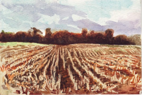
I tried this out for the first time in this watercolor of a feld of corn stubble. This was an interesting subject, because of the interplay between the human design of the parallel, evenly spaced rows of corn stubble and the organic contours of the land.


If you look closely you can see the faint pencil lines denoting the horizon, vertical center, square and diagonals. Here they are in an overlay:


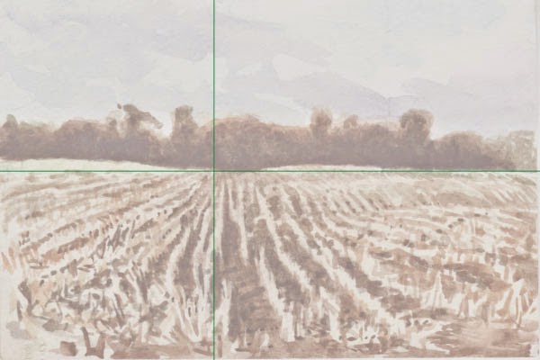
Note that the vertical line corresponds to the most vertical appearing stubble rows.


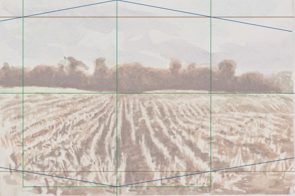
Here is the sketch in the context of the full field of view. The height of the square is about 1/6 to 1/5 of the height of the total, so the diagonal intersects the side of the square about 1/10 of the way from the top.


Having done all this prep work, I ended up still working quite freely on the painting, being much more concerned with the play of light and color than getting perfectly accurate perspective. However, it was very helpful to have the diagram for reference and probably even more valuable to have gone through the exercise. As General Dwight D. Eisenhower put it, "In preparing for battle I have always found that plans are useless, but planning is indispensable."

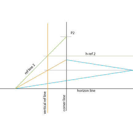
How do the diagonal vanishing points help with establishing the apparent distances between points on the ground plane? When I did the stubble painting, I only used the perspective framework as a general guide, and it was quite useful even so. Just having the central point explicitly marked on the paper really helped to keep the picture oriented. But in the back of my mind there was a structure something like this:


What looks like railroad tracks is a trick for laying out the receding distances. Basically, you start with a pair of "orthogonals" - lines converging on the vanishing point - and one of the lines pointing to a diagonal vanishing point, and set a horizontal line at their intersection. This creates a square on the ground plane as seen in perspective. Draw a diagonal between the other two corners to find the center. Draw another orthogonal from the vanishing point through the center point, and another horizontal line through the center point to cross the orthogonals and the rest of the picture. Draw a diagonal from the opposite intersection of that line through the midpoint of the farther horizontal to cross the far orthogonal. Repeat this process, climbing up the ladder of your own making towards the principal vanishing point. This is way easier to do than to explain in words, and fun in a repetitive sort of a way. Notice how you don't have to refer to the original diagonal or a vanishing point again; it's all self replicating once you do the initial setup.

When I was originally taught this trick, they left out the crucial ingredient of relating the diagonals to a specific eye height and viewing distance. You were supposed to just arbitrarily pick an angle, and the proportions would be internally consistent from then on. It is true that the result might look convincing on its own terms, but if you introduced vertical elements and needed them to change apparent size in inverse proportion to their distance on the ground plane, it wouldn't work out.


Perspective hacks II: Know when to fold 'em

As I mentioned in the first Perspective Hacks, there are two kinds of external vanishing points, diagonal and rotated. Diagonal VPs help to establish proportional apparent distances receding in space, like a tiled floor or the ties of a railroad track. Rotated VPs are used for lines or planes that are set at an angle to the viewer.
Single point or central perspective works for lines and planes that are parallel or perpendicular to the viewer; parallel lines are shown as straight and parallel to each other, and perpendicular lines converge on the central vanishing point. When a rectilinear object is at any other angle, the corner and at least two sides become visible, requiring two vanishing points.

In many cases, one or both of these points will be located very far outside the picture, creating logistical problems setting them up and using them as references. Here is one possible solution, which can "fold" a vanishing point back so it fits inside your picture, or at least onto a reasonable sized drawing board.

Set up your horizon line
Establish a vertical corner line


Choose a point "p1" on the vertical corner line.


Draw an initial diagonal "ortho 1", carried out to the edge of the paper. This can be based on sight, memory, measurement or imagination. It points to the location of our actual VP, somewhere off the paper.


Draw a horizontal line, "h-ref 1," from the point where the diagonal intersects the edge, so as to intersect the corner line and go a bit beyond it.


Measure the distance from this intersection to the ortho 1 intersection, "h1"


Mark a point "P ref" on the corner line at an equal distance "h2" below the intersection of h-ref 1.


Draw a line "folded ortho" from the intersection of ortho 1 with the edge of the paper through this mark and down to the horizon line. This line creates an angle equal to the original diagonal, but reversed.


The point where it intersects the horizon is the “folded vanishing point". It is the equivalent of setting a vanishing point outside of the picture, then folding it over to meet a point inside the picture.


Draw "ref line 1" from the folded VP up to the intersection of ortho 1 and the corner line. Note where it intersects h-ref 1.


Draw a vertical reference line intersecting this point.


This completes the basic set up. You can now use the folded vanishing point and vertical ref line to draw new orthogonals in the same vertical plane as the first.


To create a new orthogonal based on the folded VP, first mark a new point "P2" on the corner line.


Draw a line "ref line 2" from the folded VP to P2.


Where this line intersects the vertical ref line, draw a horizontal line, "h-ref 2" to the edge.


Draw a line from P2 to the intersection of h-ref 2 with the edge of the paper. This line, if carried out off the paper far enough, would intersect the actual VP at the horizon.


Repeat this process to create more orthogonals as needed.


These techniques are not without their own drawbacks. They require more steps than using "real" vanishing points, and they tend to magnify small inaccuracies. But in a situation where using external VPs is impossible or impractical, they will get the job done. The folded VP technique is still limited by the size of the paper and drawing surface and the angle of rotation - it is possible to have a angle such that even the folded VP goes out of range. Of course, you could "fold" it multiple times, but that would get even more cumbersome and prone to error. However, as with the diagonal VPs, there is a way to calculate the correct rotated angles without using vanishing points at all:
Bleep the Veeps!
How to do "two point perspective" without any points!


Perspective Hacks I

Perspective Hacks II
Perspective Hacks III
Perspective Hacks IV
Perspective Hacks V
Perspective Hacks VI

Perspective hacks III: Bleep the Veeps!

In the first Perspective Hacks we looked at the diagonal vanishing point, and how to replace it with a proportional estimate and an internally generated grid.
In the second, we explored the "folded vanishing point" technique in which the remote VP is relocated to the page and used to generate related orthogonals.
In this installment, we will learn how to set up a "two point" perspective drawing with no points at all.
Imagine that you are stuck overnight in a desolate airport, with nothing to amuse yourself but a sketchbook, a pencil, and some scratch paper. You decide to create an elaborate perspective drawing from imagination. Or perhaps you are sketching a bucolic scene, but in the middle distance is Salisbury Cathedral or similar complex structure. You wish you could use perspective to help construct it, but you have no drawing board or thumbtacks.
As with the other exercises, we start with a single orthogonal. This can be based on measurements, observation, or pictorial considerations, but will provide the basis for all related lines following.
Here we see the horizon line, central vertical line, and initial orthogonal. We are assuming this slanted line stands for a line parallel to the ground plane and rotated on its vertical axis so it appears to recede towards the horizon.


We could use the edge of the paper as a reference, but here we are using a guideline, which can make it easier to make accurate measurements or simplify proportions.


Here's were the scratch paper comes in. It can be practically any rectangular piece - a post-it note, a sheet of notebook paper, etc. Business cards or the subscription cards that come with magazines work nicely, as they are printed on heavier card stock. We are going to use this as a "ruler" to find the proportional relationship between the orthogonal and the horizon line.
First label one side of your ruler "L" for Long. It's important to keep track of which side is which. Line the ruler up with the horizon and center lines and mark it with a horizontal line at the intersection with the orthogonal. The horizontal should extend a little way across the ruler.


Now, rotate the ruler 90˚ so that the edge that was the top lines up with the guideline and the horizon line. Label this edge "S" for "Short."
Mark the intersection with the orthogonal with a horizontal line intersecting the L mark.


Draw a diagonal from the opposite corner through the intersection of the two marks. The slope of this line embodies the proportional relationship of every orthogonal parallel with the first to the horizon.


To create a new orthogonal parallel to the first and appearing to recede to the same vanishing point, start with a line on the center vertical where you want it to start.


Line up the Long side of the Ruler as before, and draw a horizontal line at the location of the mark you just made so as to intersect with the diagonal.


Rotate 90˚ and line up with the horizon and guideline. Draw a horizontal line from the intersection of the diagonal with the line you just made out to the edge of the Ruler.


Mark the guideline at this point.


Draw a line through the the two marks to the edge of the page. This is your second orthogonal.


Here's the third, constructed the same way.


For the fourth, we start under the horizon line.


Turn the ruler upside-down and make a horizontal line intersecting the diagonal. Here, we used the opposite side to make the mark. There are several ways you could accomplish the same thing, depending on the size and shape of your Ruler.


Rotate ruler so that what was the top is lined up with the Guideline. Draw a horizontal line through the intersection with the diagonal and mark the guideline as before.


Draw a line through the two points. This is another orthogonal parallel to the others, but originating below the horizon line and pointing up the same implied vanishing point.


Perspective Hacks I

Perspective Hacks II
Perspective Hacks III
Perspective Hacks IV
Perspective Hacks V
Perspective Hacks VI


Perspective hacks IV: The Box

As I mentioned in the first Perspective Hacks, I was very taken with Bruce McEvoy's model of a simplified perspective situation:

Having come into possession of a clear plastic cube, I decided to create a physical model of it.

The first step was to place the picture plane so as to divide the cube in half, so that the distance from the ground plane to the centerpoint, one half the cube's height, would equal the distance from the viewpoint to the picture plane.


I cut the picture plane out of an old CD jewel box, inscribed the horizon line, vertical center line, and circle of view on it, and mounted it at the halfway point.

On the facing side of the same piece, I made a line from the middle of the bottom edge to the centerpoint, representing the viewer's eye height and viewpoint.


I made a rectangular opening in a square sheet of paper to mask off part of the picture plane, leaving a window to reveal the space on the far side. Note that the center of the picture window is not the same as the center of vision.
The window could be any arbitrary size, shape, or position in the plane, although usually the center of vision (the main vanishing point) is somewhere near the center of the picture.


The space behind the window is defined by two inclined planes at 45˚, meeting at the horizon and inscribed with a grid of orthogonals and diagonals.


Figuring out how to plot this grid was a puzzle, and led to some interesting insights into the wider subject of space division in a rectangle, so I'll address that in a separate installment. Basically, the inclined planes mimic the appearance of infinite ground and sky planes receding to the horizon, but contained in the half-cube opposite the viewpoint.

I tried to get a photo from as close as possible to the actual viewpoint. It should give the impression of looking into 3D space (on a really gloomy, depressing day in some sort of post-apocalyptic dystopia).


Perspective hacks V: Villard's Railroad

In Perspective Hacks IV: The Box, I mentioned the problem of plotting a perspective grid on a 45˚ inclined plane to represent the view through the window in the picture plane. The box has two mirror image planes meeting at the horizon line; here is just the bottom half for simplicity's sake:


I wasn't sure how to approach the problem of plotting the grid at an angle until I tried drawing out the arrangement in a side view. 


Here, the square on the left represents the box, with the viewpoint at the halfway mark on the left side. Points on the ground at regularly spaced distances D1 - D5 would reflect rays of light to the viewer's eye, intersecting the Picture Plane at the bottom for D1, the 1/2 point for D2, the 1/3 point for D3, and so on. When the Inclined Projection Plane is placed at a 45˚ angle between the Picture Plane and the Principal Point, the rays would intersect it at bottom for D1, then 2/3 for D2, 2/4 (or 1/2) for D3, 2/5, 2/6 (1/3), and so on.

Here is where my perspective wanderings finally looped back to the Hor:ratio project. One of the proportional tools included in Hor:ratio is the Armature of the Rectangle, a simple yet profound pattern of diagonals that creates fractional divisions of each side by 2, 3, 4, 5.


See how the simplified armature corresponds to the lower right quadrant of the square in the side view. The division of the square by 3 at the intersection of the ray with the diagonal also divides the diagonal itself 2/3 from the top.


Using this knowledge, I could find the 2/3 point on the inclined plane and use it to build the grid according to the Railroad Track Hack.

For some reason I had never noticed the similarity between the Railroad Track Hack and Villard's Diagram, which I had also come across in course of the Hor:ratio research, Initially, I had seen it applied to particular proportional settings, such division by 9, used in book page layouts. Suddenly I realized that it could be used to divide a rectangle by any fraction! 
Starting with one half:


take a diagonal from the intersection of the 1/2 line and the edge up to the far corner


draw a horizontal line through the intersection with the opposing main diagonal to divide by 1/3


draw another diagonal from the intersection of the 1/3 line and the edge up to the far corner


draw a horizontal line through the intersection with the opposing main diagonal to divide by 1/4


Repeat for 5,6,7 and so on. 


Thus, we can divide the rectangle into an infinite number of smaller and smaller fractions. 
However, we don't have to plod though all of the steps to reach a desired fraction . If we combine the principals of the Armature of the Rectangle with Villard's Diagram, we can cut out steps and simplify the design by leapfrogging to the nearest simple division and building from there.


The procedure for building the VD is the same as for the RTH, but instead of thinking of it as equal distances receding in space, we see it for what it is - the progressive division of the rectangle into proportionately smaller fractions. This is indeed the principle upon which perspective is based: The apparent size of an object diminishes in direct proportion to its distance from the observer.


Perspective Hacks I

Perspective Hacks II
Perspective Hacks III
Perspective Hacks IV
Perspective Hacks V
Perspective Hacks VI